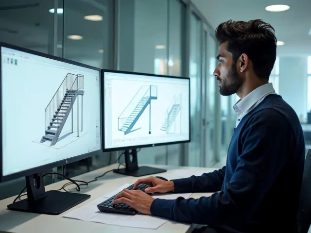


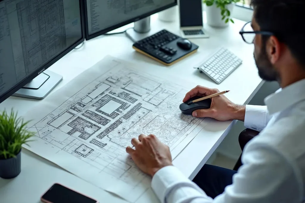
CAD conversion is the process of turning paper drawings, scanned blueprints, PDFs, and image files into accurate, editable CAD files, usually AutoCAD DWG or DXF, and sometimes Revit or other 3D formats. For architecture, engineering, and construction firms, it is how decades of legacy drawings, consultant PDFs, and as-built records become working files your team can measure, edit, and build on.
Renovations, tenant improvements, facility upgrades, and additions almost always start with existing drawings, and those drawings rarely arrive as clean native CAD. This guide explains what CAD conversion is, the main types, how the process works, what affects accuracy, which file formats to ask for, and how to prepare a conversion project so the results are ready for production. If you want the work handled inside your own workflow, dedicated CAD drafters can take on conversion alongside your everyday drafting.
CAD Conversion: Quick Answers
- What is CAD conversion? Recreating drawings from paper, scans, PDFs, or images as editable CAD files with true geometry, layers, text, and dimensions.
- Can a PDF be converted to CAD? Yes. Vector PDFs exported from CAD software convert with high fidelity, while scanned (raster) PDFs are redrawn from the image.
- What is the difference between raster and vector? A raster file is a grid of pixels, like a photo of a drawing. A vector file stores lines, arcs, and text as objects you can select and edit.
- Is automatic conversion good enough? Auto-trace tools are a fast starting point, but production-quality results usually come from manual redrafting or a careful cleanup of the traced output.
- What files do you get back? Most AEC firms ask for DWG, often with DXF or PDF copies. Projects that move into BIM can be rebuilt as Revit models.
- How long does it take? It depends on the number of sheets, the source quality, drawing complexity, and the level of detail required.
What Is CAD Conversion?
At its simplest, CAD conversion takes a drawing that you can only look at and turns it into a drawing you can work with. A scanned floor plan shows walls, but you cannot select a wall, change its length, or move a door. Once the same plan is converted, every wall is a line on the right layer, every dimension is editable, and the drawing can be scaled, plotted, referenced, and shared like any other CAD file.
The term covers several related jobs:
- Paper to CAD: physical prints, vellums, and hand-drafted sheets are scanned and redrawn in CAD.
- PDF to CAD: PDF drawing sets from consultants, owners, or archives are converted into DWG or DXF.
- Raster to vector: image files such as TIFF, JPG, and PNG are traced into vector linework.
- Format-to-format conversion: files move between CAD platforms, for example from MicroStation DGN to AutoCAD DWG.
- 2D to 3D conversion: 2D plans, sections, and elevations become a 3D model or a Revit model for BIM workflows.
The Library of Congress format descriptions for DWG and DXF are a useful reference if you want background on why these two formats became the common language of 2D drafting.
Why AEC Firms Convert Drawings to CAD
Firms convert drawings for practical, project-driven reasons:
- Renovation and adaptive reuse: existing building drawings become the base for demolition plans, new layouts, and permit sets.
- Additions and expansions: accurate existing conditions let the new design tie in cleanly.
- Facility and property management: owners want floor plans they can update as spaces change.
- Consultant and owner PDFs: teams often receive only PDFs and need editable backgrounds to coordinate their own work.
- Archive digitization: rolled drawings and flat files take space, fade, and are hard to search. Digital CAD files are easier to store, back up, and find.
- Standards cleanup: older CAD files are brought up to the firm’s current layers, text styles, and title blocks.
In every case, the goal is the same: a reliable, editable starting point that saves your design team from redrawing existing conditions under deadline pressure.
Raster vs. Vector Files: Why the Source Matters
The single biggest factor in a conversion project is the type of source file.
| Source type | What it is | What conversion involves |
|---|---|---|
| Vector PDF | A PDF exported from CAD software, with selectable lines and text | Geometry can often be imported, then cleaned up, layered, and scaled |
| Raster PDF or image | A scan or photo saved as pixels (PDF, TIFF, JPG, PNG) | Linework is traced or redrawn from the image, then checked against dimensions |
| Paper drawings | Physical prints, blueprints, or vellum sheets | Sheets are scanned at high resolution first, then redrawn as raster files |
| Native CAD in another format | DGN, older DWG versions, or other CAD formats | Files are translated, then layers, blocks, and fonts are mapped to your standards |
A quick test tells you which kind of PDF you have: open it and try to select a single line or a word. If you can, it is likely a vector PDF. If the whole page highlights as one image, it is raster, and the drawing will need to be redrawn.
Manual Redrafting vs. Automatic Conversion
Software can trace raster images automatically, and some PDF import tools bring vector geometry straight into CAD. These tools are useful, especially for clean vector sources, but their output usually needs work before it is ready for production. Traced files often contain broken lines, duplicate entities, text that comes in as tiny line segments, and arcs approximated by many short lines.
Manual redrafting takes a different approach. A drafter uses the scan or PDF as a reference underlay and redraws the drawing with proper CAD objects: continuous lines, true arcs and circles, editable text, dimension styles, blocks for repeated elements, and the correct layers. The result is lighter, cleaner, and behaves like a drawing created in CAD from the start.
Many experienced teams combine both methods: they import or trace what they can, then redraft and clean up the rest. The right mix depends on the source quality and how the drawing will be used.
How the CAD Conversion Process Works
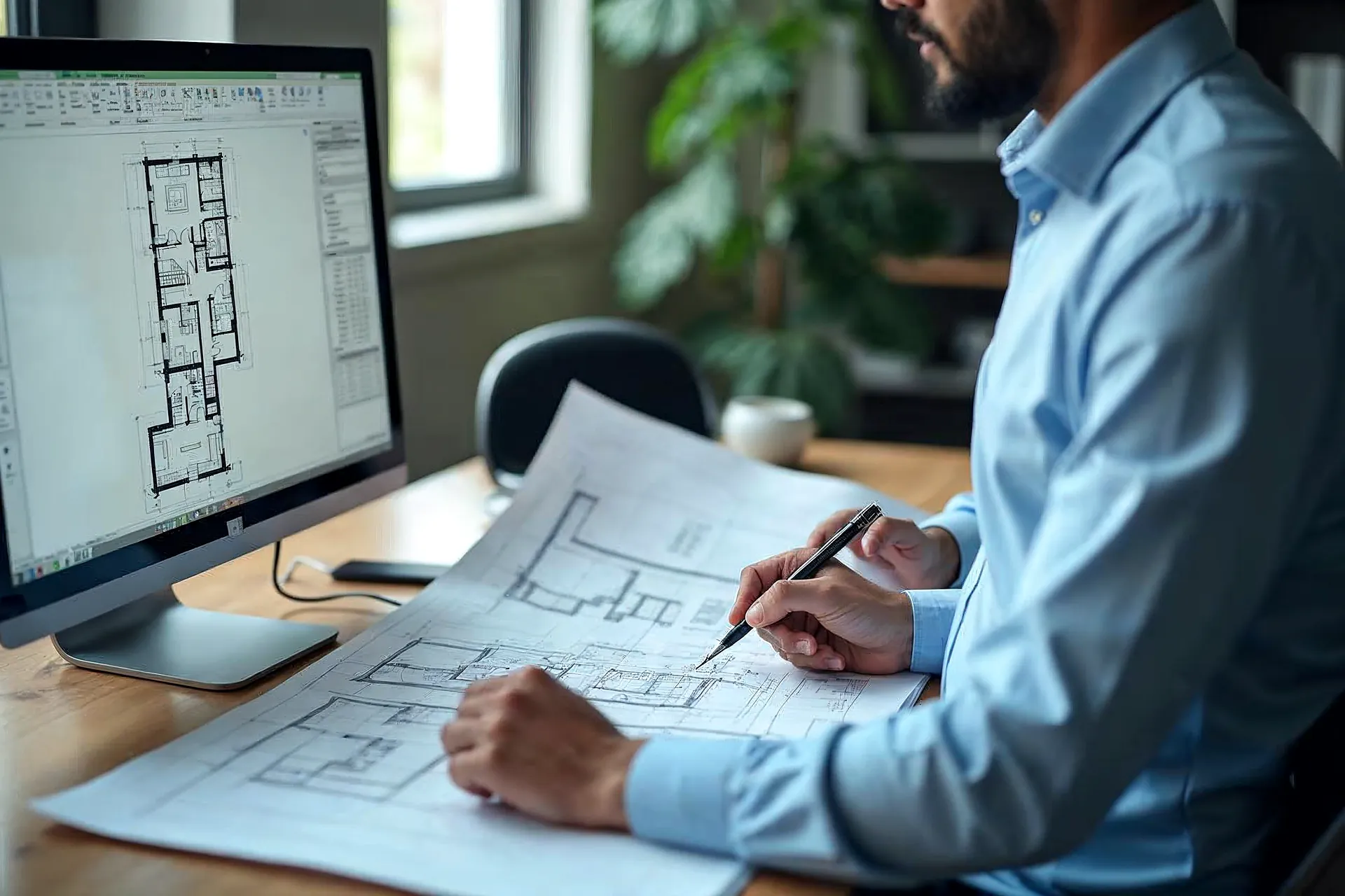
A well-run conversion project follows a clear sequence.
1. Gather and Review the Source Drawings
The team collects every sheet, checks scan quality, notes missing or illegible areas, and confirms which drawings are in scope. This is also when the drawing standard, output format, and CAD version are agreed.
2. Scan and Prepare the Files
Paper drawings are scanned at a resolution high enough to read fine linework and small text. Scans are straightened and cleaned so the image is easy to trace accurately.
3. Set Up Scale and Standards
The drafter calibrates the underlay to a known dimension, then sets up layers, text styles, dimension styles, and title blocks based on your CAD template or a recognized standard such as the United States National CAD Standard.
4. Redraw the Geometry
Walls, grids, doors, windows, structural elements, site features, annotations, and dimensions are redrawn as clean CAD objects. Repeated items become blocks, and hatches and linetypes are matched to the original intent.
5. Check the Drawing Against the Source
The converted file is overlaid on the source to confirm alignment, written dimensions are checked against the drawn geometry, and text is proofread. Any conflict in the original, such as a dimension that does not match the drawing, is flagged for your team to decide.
6. Deliver and Organize the Files
Files are delivered in the agreed format and version, with consistent naming and sheet organization, so they drop straight into your project folders.
What Affects CAD Conversion Accuracy
Converted drawings are only as reliable as the information behind them. These factors have the biggest influence on accuracy:
- Source quality: sharp, high-resolution scans and vector PDFs give the best results. Faded, folded, or low-resolution sheets take more interpretation.
- Written dimensions: drawings with complete dimensions can be rebuilt to true size, rather than measured off the image.
- Scale and distortion: older prints can stretch or shrink over time, and scans can skew, so calibration matters.
- Drawing standards: clear instructions for layers, line weights, and text styles produce files that match your existing work.
- Level of detail: a simple background plan takes far less effort than a fully annotated construction drawing with every detail redrawn.
For renovation work, legacy drawings record what was designed, so pairing converted drawings with field verification or laser scanning gives designers the most dependable base. Once that base is set, the same team can move on to detailed deliverables such as shop drawings.
File Formats to Ask For
Being specific about deliverables saves rework later. Common requests include:
- DWG: the native AutoCAD format and the default for most AEC drafting.
- DXF: an interchange format that many CAD, CAM, and GIS programs can read.
- DGN: the MicroStation format, often required by transportation agencies and some owners.
- RVT: a Revit model, when the converted drawings will become the basis for BIM.
- PDF: plot-ready copies for review and record.
Also confirm the CAD version, units (imperial or metric), whether you want model space and layouts set up, and whether external references should be bound or kept separate. DWG and DGN files open in many programs beyond their original software, thanks in part to the Open Design Alliance, an industry group that develops shared tools for reading and writing both formats.
From 2D Drawings to 3D and BIM Models
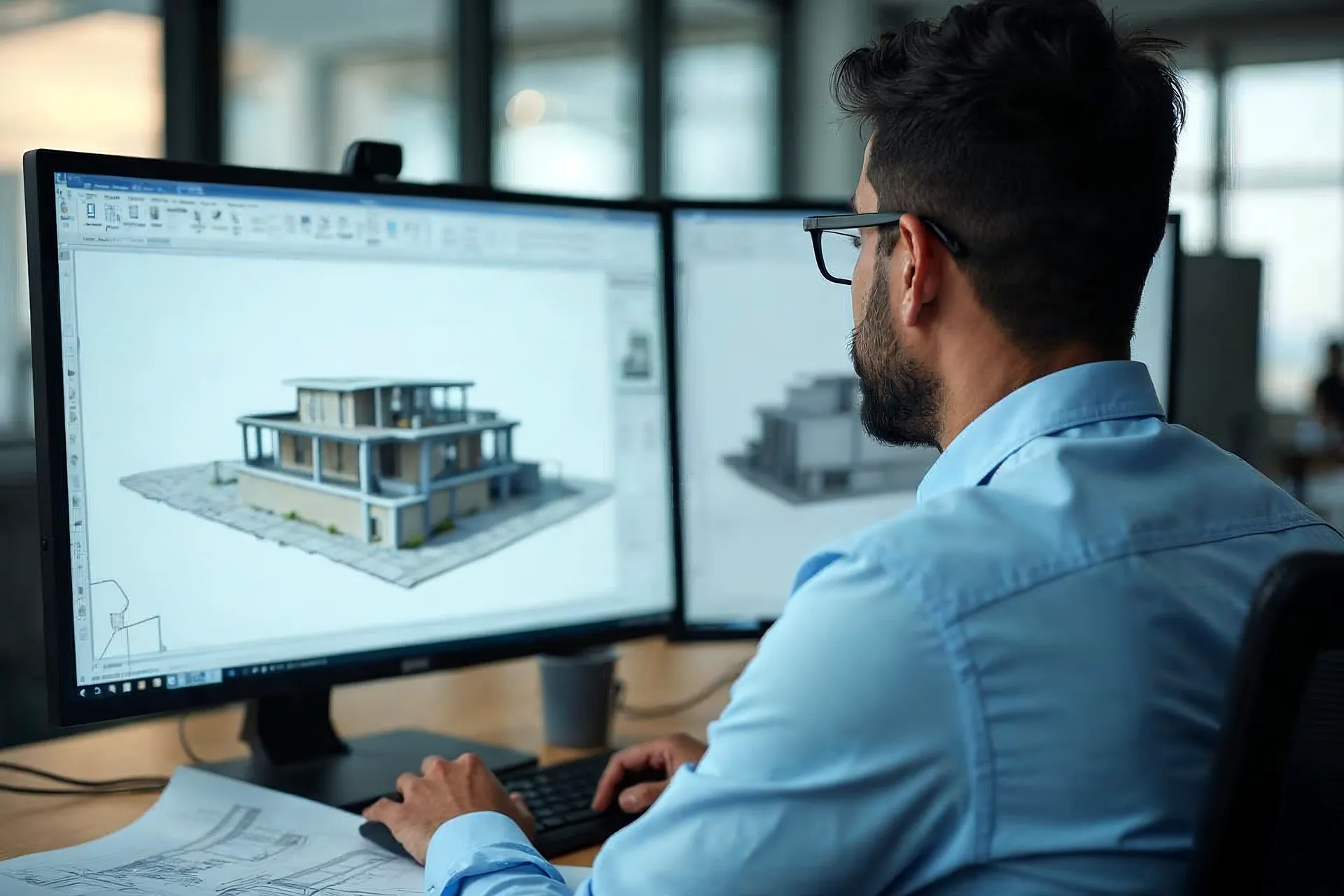
Many conversion projects now go one step further. Instead of stopping at 2D DWG files, firms use converted plans, sections, and elevations to build a 3D model or a Revit model of the existing building. That model becomes the base for design options, coordination, quantity takeoffs, and facility management.
Converting to BIM takes more information than 2D conversion, because the model needs heights, wall types, floor levels, and other data that a flat plan may not show. Sections, elevations, and field data fill those gaps. Standards such as the National BIM Standard-United States help teams agree on what the model should contain. If you are planning this kind of work, it helps to understand what a BIM specialist does and how the role differs from 2D drafting.
How to Prepare a CAD Conversion Project
A little preparation makes any conversion faster and more accurate:
- Collect the best available source: original prints scan better than copies of copies, and vector PDFs beat scans.
- Mark up what matters: highlight the sheets, areas, and details that must be converted and those that can be skipped.
- Share your CAD template: send your layer standards, title block, text and dimension styles, and a sample of a finished drawing.
- Define the level of detail: say whether you need a clean background, a full construction-level drawing, or a 3D model.
- Confirm the deliverables: list the file format, CAD version, units, and naming convention.
- Plan a review step: have someone on your team spot-check the first few sheets before the rest of the set is converted.
If your firm converts drawings regularly, it can be more efficient to have the work done by people who already know your standards. Our guides on when a dedicated CAD drafter makes sense and how to manage a remote CAD team cover how firms set this up.
CAD Conversion Support With Remotation
Remotation places dedicated, full-time CAD drafters and BIM specialists with US architecture, engineering, and construction firms. Each professional works only for your firm, learns your CAD standards, and handles conversion work alongside your everyday drafting, from redrawing legacy plans to building Revit models of existing buildings. Remotation handles recruitment, HR, and payroll, and the team works from our Karachi office, managed from Houston, giving you experienced drafting support at a fraction of the cost of local hiring.
To add capacity, explore our dedicated CAD drafters and BIM specialists, review pricing for dedicated AEC professionals, or book a 15-minute intro call.
Frequently Asked Questions
What is CAD conversion?
CAD conversion is the process of turning paper drawings, scans, PDFs, and image files into editable CAD files, such as DWG or DXF, with real lines, layers, text, and dimensions instead of a flat picture.
Can you convert a PDF to an editable AutoCAD drawing?
Yes. A vector PDF exported from CAD software can often be imported and then cleaned up and layered. A scanned PDF is an image, so its linework is traced or redrawn by a drafter to create an accurate DWG.
What is the difference between raster to vector conversion and redrafting?
Raster to vector conversion usually refers to tracing a pixel image into linework, often with software. Redrafting means a drafter rebuilds the drawing with proper CAD objects using the image as a guide. Redrafting produces cleaner files that are easier to edit.
How accurate is CAD conversion?
Accuracy depends on the source. Clean vector PDFs and well-dimensioned drawings can be rebuilt to true size, while faded or distorted scans rely more on calibration and interpretation. Checking written dimensions against the drawn geometry is the best way to confirm results.
Can 2D drawings be converted into a Revit or BIM model?
Yes. Plans, sections, and elevations can be used to build a 3D or Revit model of an existing building. The more height and material information the drawings contain, the more complete the model will be.
What should I send to start a CAD conversion project?
Send the source files, a list of the sheets in scope, your CAD template or standards, the required file format and version, the level of detail you need, and your preferred delivery schedule.
How do construction firms manage large sets of converted CAD files?
Most firms use a consistent file naming convention, a shared project folder structure, external references for backgrounds, and a single CAD standard so every converted file looks and behaves the same as the rest of the drawing set.